Mtd BCR4 BCK Bedienungsanleitung
Stöbern Sie online oder laden Sie Bedienungsanleitung nach Werkzeug Mtd BCR4 BCK herunter. MTD BCR4 BCK User Manual Benutzerhandbuch
- Seite / 12
- Inhaltsverzeichnis
- LESEZEICHEN
Inhaltsverzeichnis
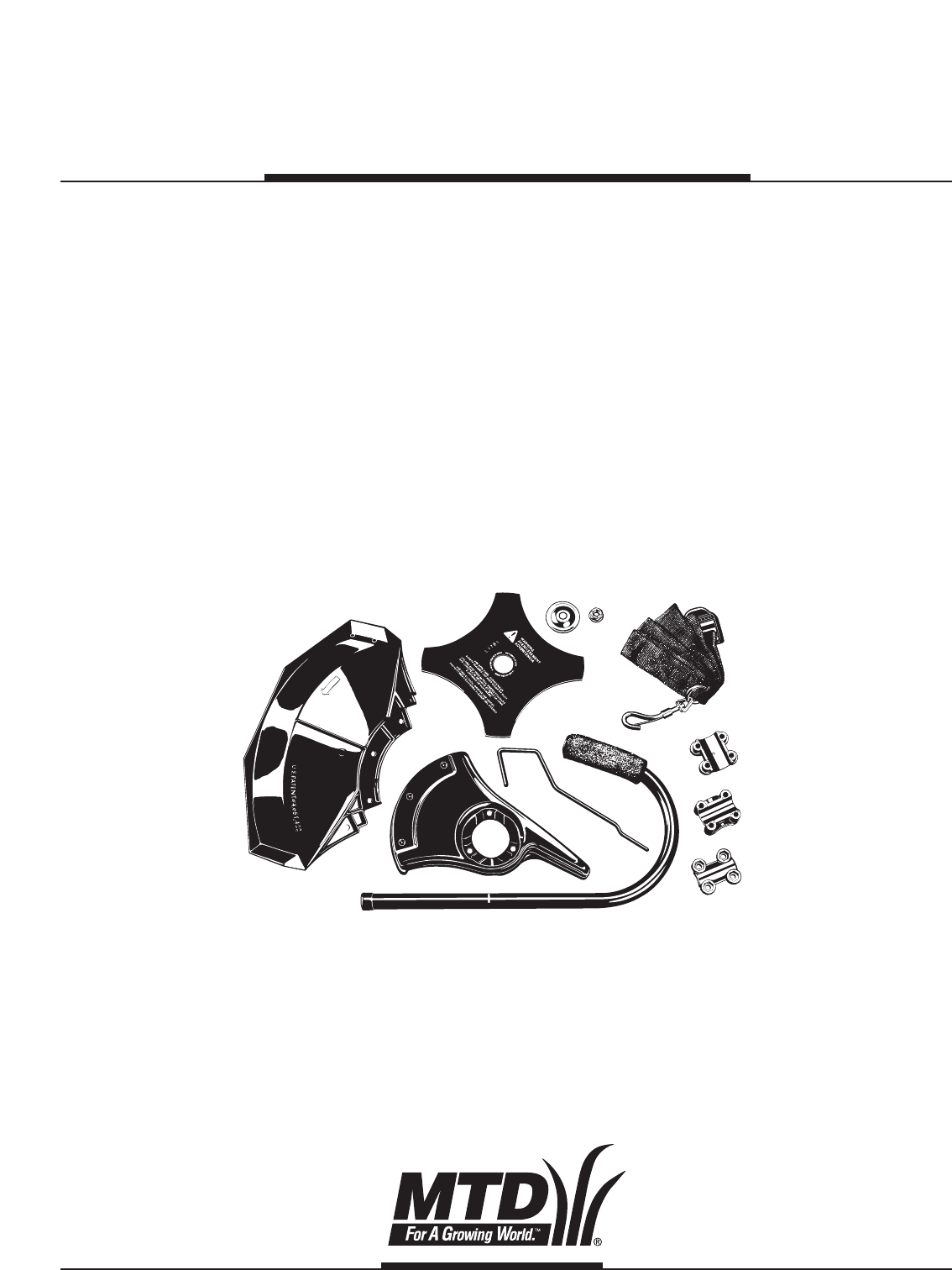
BCR4 BCKBrushcutter KitOPERATOR’SMANUALIMPORTANT MANUAL DO NOT THROW AWAY
10FIGURE 18ASSEMBLY INSTRUCTIONSWARNING: If the cutting blade is off-center,the unit will vibrate, and the blade may flyoff, which can cause serious p
11FIGURE 216. Remove the locking rod.7. Install the cutting attachment shield. See Removeand Install Cutting Attachment Shield.WARNING: To avoid serio
FIGURE 24OPERATING INSTRUCTIONSUSING THE CUTTING BLADEWARNING: Always wear eye, hearing, foot,body protection and the harness to reducethe risk of inj
2Thank YouThank you for purchasing this quality product. Thismodern outdoor power tool is designed to providemany hours of useful service. You will fi
RULES FOR SAFE OPERATION3SYMBOL MEANINGWARNING: Failure to obey a safetywarning can result in serious personalinjury to yourself or to others. Alwaysf
RULES FOR SAFE OPERATION4• Keep hands, face, and feet at a distance from allmoving parts. Do not touch or try to stop the cuttingattachment when it is
RULES FOR SAFE OPERATION5SAFETY AND INTERNATIONAL SYMBOLSThis operator's manual describes safety and international symbols and pictographs that m
FIGURE 2FIGURE 3ASSEMBLY INSTRUCTIONS6INSTALL THE BRUSHCUTTER KITThe Brush Cutter Kit consists of:• J-handle and hardware• Harness• New cutting attach
FIGURE 8FIGURE 7FIGURE 6FIGURE 5FIGURE 47ASSEMBLY INSTRUCTIONSAdjustment7. Loosen the screws so that the J-handle easilymoves in the clamp assembly. D
FIGURE 12FIGURE 98ASSEMBLY INSTRUCTIONSFIGURE 11REMOVE THE CUTTING ATTACHMENTNOTE: To make removing or installing the cuttingblade or cutting attachme
FIGURE 149ASSEMBLY INSTRUCTIONSFIGURE 15FIGURE 16FIGURE 17FIGURE 13INSTALL THE NEW CUTTINGATTACHMENT SHIELD MOUNT Install the cutting attachment shiel
Verwandte Produkte und Handbücher für Werkzeug Mtd BCR4 BCK


 (60 Seiten)
(20 Seiten)
(44 Seiten)
(68 Seiten)
(20 Seiten)
(24 Seiten)
(64 Seiten)
(36 Seiten)
(0 Seiten)
(0 Seiten)
(6 Seiten)
(20 Seiten)
(7 Seiten)
(12 Seiten)
(12 Seiten)
(16 Seiten)
(20 Seiten)
(10 Seiten)
(14 Seiten)
(12 Seiten)
(60 Seiten)
(20 Seiten)
(44 Seiten)
(68 Seiten)
(20 Seiten)
(24 Seiten)
(64 Seiten)
(36 Seiten)
(0 Seiten)
(0 Seiten)
(6 Seiten)
(20 Seiten)
(7 Seiten)
(12 Seiten)
(12 Seiten)
(16 Seiten)
(20 Seiten)
(10 Seiten)
(14 Seiten)
(12 Seiten)
© 2020, manymanuals.de. Alle Rechte vorbehalten. | 2.275 s |
 Manymanuals.com
 Manymanuals.de
 Manymanuals.fr
 Manymanuals.it
 Manymanuals.pl
 Manymanuals.cz
 Manymanuals.es
 Manymanuals-pt.com
Kommentare zu diesen Handbüchern